|
Radar
Station
The
Radar Station was located on the left side of the aircraft behind
the Central Fire Control area. It was an exact duplicate of the
navigator’s station plus the bulky elements of the AN/APQ13
Radar System. It was the most spacious compartment on the aircraft
and provided sack space for exhausted crew members on the way
back to base when out of range of enemy aircraft. There were no
bunks, though interior photos often showed a tier of bunks. There
was only floor space on which to stretch out. Periodically the
Squadron Radar Officer would fly with one of the crews setting
up his radar countermeasure equipment next to the Radar Observer.
This cut down on the sack space. Fulfilling his RCM role he would
jam enemy radar electronically and also measure the enemy wave
lengths to determine the length of “rope” (window),
the aluminum strips that were released on the bomb run to flood
the enemy radar screens with false images which reduced the effectiveness
of antiaircraft batteries.
The
signals generated by the system’s magnetron were transmitted
by a rotating dish antenna housed in a Radome mounted on the belly
of the aircraft between the two bomb bays. The Radome could be
lowered during a bomb run to avoid signal interference with the
open bomb bay doors. The signals were reflected back to the antenna
after bouncing off targets in the field of transmission. The returned
signals formed an image on a Cathode Ray Tube called a Plan Position
Indicator (PPI), See Photo.
The
screen measured six inches in diameter. The aircraft’s position
was at the center of the screen and the three-inch sweep from
the center ranged out to 100 nautical miles. There were five range
settings from 100NM down to a manual zoom setting. The screen
was overlaid with a transparent grid. One axis served both as
a course marker and a bearing marker to determine the azimuth
of any target visible on the screen. The screen was a repeat display
of the Gyro Fluxgate Compass, with the outer ring calibrated in
degrees and the True Heading marker illuminated. The magnetic
variation for the area was preset into the compass saving pilot
and navigator the need for this correction. The screen was oriented
due north but could also be oriented with the true heading marker
pointed to the top of the screen.
The
potency of the microwave signals was well recognized by crew members
and concerns emerged over the potential health hazards from continuous
exposure to these emanations. It was feared that cancer, leukemia,
anemia and sterility were possible consequences. Sterility equated
to virility and countermeasures were proposed. One involved utilization
of the flak suit. After the first few missions crew members opted
to use only the lower panel, sitting on it protecting their bottoms
and manhood. It was suggested that lead plates be substituted
for the steel plates to provide a radiation shield. Concerns evaporated
when common sense took over. Returning signals were either absorbed
by the antenna or bounced off the skin of the aircraft and reflected
away. This was a rationalization, which provided the comfort to
dismiss the concern. There is no record of any scientific test
of this theory.
|
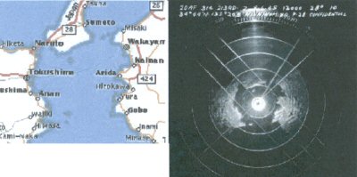
Southern
Sector of Bay Serving Kobe and Osaka |
Above is a map of South Osaka Bay and at right
the bay displayed on the Plan Position Indicator (PPI).
The
range is set at 50NM and the concentric circles on the movable
grid are 10 NM wide. The aircraft is at the center of the screen,
right in the middle of the bay. At the top the compass ring is
visible calibrated in degrees. The true heading marker shows the
aircraft on a true heading of 28 degrees. The small black circle
in the center is caused by the absence of signals from the distance
of the plane’s altitude of 13,000 feet, approximately 2
nautical miles. There is also ground clutter at the center as
the early return signals are received.
The
bearing marker on the grid could be moved to any point on the
screen to get a true bearing. A range circle was created and moved
to the point to measure distance in feet or nautical miles. A
slight adjustment had to be made for slant range depending on
altitude. The result was a fix.
The
range circle in the above image is at the outer edge of the illuminated
area in the center. It is set at a range of 6.42NM (38,009 feet),
the slant range which corresponds to an initial sighting angle
to target of 70 degrees in preparation for the bomb run. This
value is from calculations made today with the few facts available.
The
maximum range of 100 NM was ideal for navigation. In addition
to images the APQ13 could pick up a beacon signal. Our beacon
transmitter was located on the northwest tip of Guam. As soon
as the beacon signal appeared we switched to Image and watched
Guam come into view and get ever closer.
The
system was a complete navigation tool, but the bombing function
involved teaming up with the Bombardier and the Norden Bombsight.
|